Aerodynamic Platform Control
Please enjoy the 2-minute summary gallery below, or scroll further to explore my work in greater detail
Aggressive aerodynamics packages are very sensitive to the attitude and orientation of the vehicle, and perform best when kept inside a tight operating window. These stiff ride requirements often clash with need for a compliant suspension to maintain mechanical grip over the track surface. In this page, I will cover the steps taken to develop the ride platform targets for the 2020 Clemson FSAE vehicle.
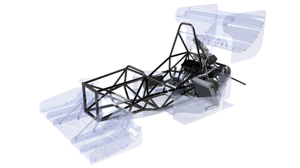
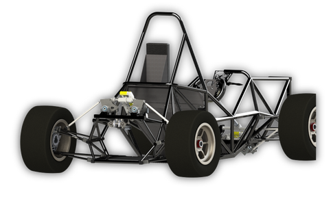
The Tiger22 Aero Package
Project Scope
Clemson's first aerodynamics package was implemented in 2017, and the relatively young division still lacks the CFD infrastructure to fully characterize an aerodynamic concept. In the past this has prevented any meaningful platform control analysis, but recent development of an automated full-car CFD script has enabled long-overdue forays into aerodynamic performance sensitivity. A proper characterization would map the car's aerodynamic performance (downforce, drag, and center of pressure) for various speeds, ride heights, pitch, and roll angles, but the only available data for the moment was speed and pitch-angle mapping.
The available scope of the project is constrained by this key limitation, but there is still meaningful work that can be carried out while the aerodynamics division grows their understanding of the package. This mainly consists of exploring the effect of center of pressure migration under pitch on the performance and stability of the vehicle. With little previous data to refer to, it is difficult to define a definitive "stability target". Instead, the goal is to create a baseline characterization and search for the threshold at which these characteristics diverge to set an upper limit pitch target. This would be combined with existing testing data to generate a complete set of rate and damping targets for the various suspension modes. The final step was to evaluate a set of feasible suspension configurations to select the concept best suited to meet as many of these targets as possible.
Center of Pressure Migration Study
Exploration of Center of Pressure (CoP) migration effects focused on outright braking performance and cornering stability under pitch motions. This was evaluated using a two-track vehicle model with linearized kinematics representation and nonlinear, load-sensitive tires.
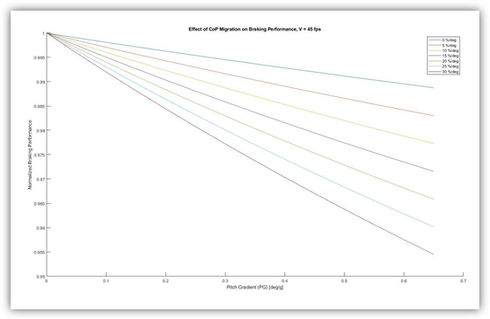
Braking performance was a fairly straightforward exploration. Even though total downforce increased with forward pitch angle, this increase was concentrated on the front wing. As the downforce distribution shifted forward, rear tire lock-up became the limiting factor for total braking performance.

This turned out to be a consistently linear effect which became more pronounced at higher velocities. No points of significant divergence were apparent. While the fall-off in brake performance could be addressed with a brake-bias adjustment, we elected to favor low speed brake balance where aero effects are limited.
Although braking performance is incredibly important, maintaining vehicle drivability was a larger priority for me. These metrics were defined using the classical linearized control derivatives for stability, control and response. I evaluated these characteristics across a range of longitudinal acceleration, to represent on track braking and acceleration scenarios. Exploring how these derivatives propagate would provide key insights on how vehicle behavior evolves in a corner entry or corner exit scenario.
First, I studied a vehicle with no aero package in order to create a baseline to compare against:
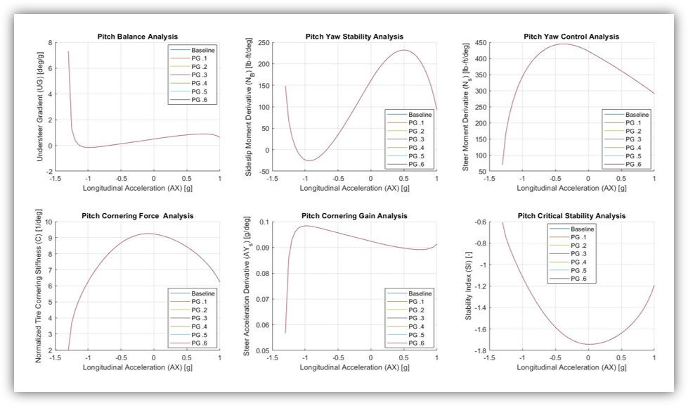
All of these metrics play an important role in predicting vehicle response to driver inputs. However, my largest priority was to avoid instability under extreme acceleration events. With this in mind, I gave the highest weight to the stability index (bottom right) and yaw returning moment derivative (top middle). With most of the plots, it is evident that mild longitudinal weight transfer has consistent, predictable effects on the balance and stability of the vehicle. On the extreme ends of the x axis, these effects diverge sharply as tires approach their saturation limit, and have very little leftover cornering force available.
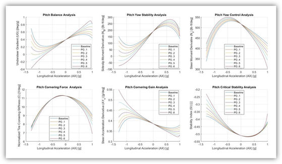
Using preliminary CFD results, I created a conservative estimate for CoP migration, which varied roughly linearly with pitch angle, and incorporated that relationship into the model. The plots were generated again, for a full range of predicted track speeds and pitch gradients (units in deg/g).

This example was taken at 45 mph, near the top end of speeds achieved on a typical autocross course.
Here it is evident that increasing the pitch graident, and therefore the total CoP migration, shifts the end behavior of the curves. The most interesting results were in metrics pertaining to vehicle balance, where after a certain pitch gradient the curve would actually inflect and change shape. This indicates that the vehicle will no longer behave in a predictable manner, and outlines a clear threshold to avoid in order to maintain consistent drivability characteristics.
In order to double check the validity of these results, I carried out a sensitivity analysis to understand which parameters had the greatest effect on the control derivatives - for example, the plots below compare the Stability Index sensitivity for extreme variations in rear camber gain:
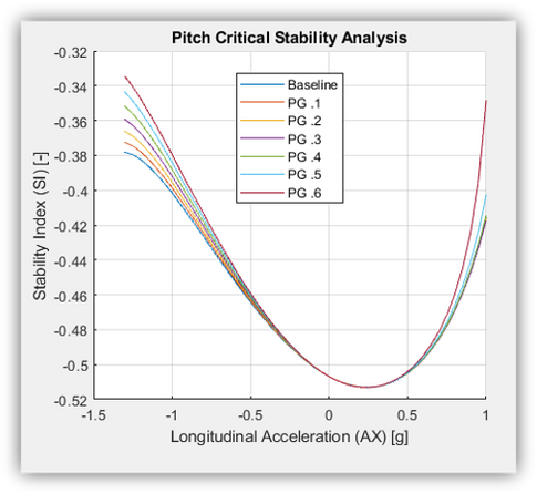
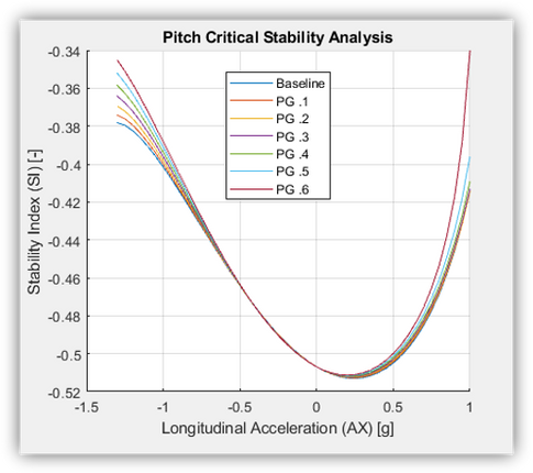
Stability Index propagation with 170% rear camber compensation
Stability Index propagation with 70% rear camber compensation
By contrast, the next two plots compare different rates of CoP migration, and demonstrated a much more significant effect:
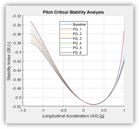

Stability Index propagation, with 16% max CoP frontward shift
Stability Index propagation, with 8% max CoP frontward shift
Center of Pressure migration was far and above the most significant variable in determining the stability of the vehicle across the full range of acceleration. After analyzing the inflection points on the derivative plots, a pitch gradient of 0.4 deg/g was determined as the threshold after which divergent vehicle behavior would occur. In order to account for tire deflection and overshoot, a final kinematic pitch gradient target of 0.32 deg/g was set.
Pitch Center and Ride Rates
With a pitch gradient target selected, and preliminary downforce predictions set, it was time to select a target heave stiffness and pitch center location. The two primary constraints were the maximum allowable pitch gradient, determined above, and the additional heave stiffness requirements to manage ride height at high speed. The range of potential solutions is summarized in the plot below:
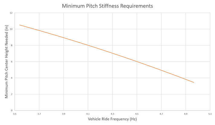
This raised an issue for us. Previous vehicle ride frequencies rarely exceeded 3.5 Hz, but increased platform stiffness demands due to the significant aerodynamic development brought the need for a prohibitively high pitch center (equivalent to over 90% anti-dive!)
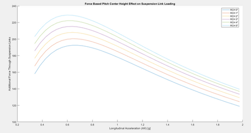
Drastically increasing pitch center height can bring many unwanted side effects, including reduced ride quality and increased tire scrub from wheelbase change. Higher pitch centers also increase braking torque loading through the suspension links, demonstrated in this plot. Lastly, a high pitch center can sometimes lead to caster change under braking, which can introduce an extra variable of complexity in managing steer-camber characteristics of the kingpin axis.
Blindly increasing ride stiffness was also not seen as a preferential alternative, though we currently lack meaningful data to predict when a suspension will become "too stiff" and lose mechanical grip. To work around this scenario, we explored the possibility of shifting the pitch center forward, to improve the consistency of front wing height variation and reduce the overall pitch requirements of the vehicle:

It was ultimately decided to shift the pitch center 20% forward of the center of gravity, at a height of 2.5 inches off the ground. This enabled us to run a more reasonable ride frequency of 4.6 Hz, while reducing loading in the suspension links by up to 15 percent when compared to a more centered alternative. While this raised the rear center of gravity under braking events, the stability effects were less significant than the CoP migration improvement, in part thanks to the superior load sensitivity of the R25B tire compound.
With pitch and ride rates finalized, a roll gradient target of 0.5 deg/g was identified as the bare minimum to protect all aerodynamic components, accounting for tire deflection and overshoot. Without extra information on the sensitivity of the aero package to roll, adjustment range was outlined as a key criteria moving forward.
Damping Targets
Next it was time to narrow in on the desired range of available damping. For this car we focused on three primary modes of body motion: Pitch, heave, and roll. As a starting point, we built off of previous work done in 2019 with the help of Ohlins USA and their 4 post shaker rig.
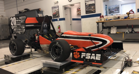
As part of a technical partnership that we formed in 2019, we had the opportunity to spend a weekend at their Henderson, NC facility with their experienced technicians.

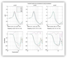
While there, we ran sine wave input tests to characterize the frequency response of the vehicle, as well as random road profile tests to evaluate the normal load variation across a typical road surface.
With their guidance and expertise, we were able to refine our suspension setups to minimize various characteristics such as tire load variation, front/rear suspension phasing, and body amplitude response. By the end of the weekend, we walked away with a complete setup catalog consisting of four setups: "Baseline" (our best setup up until then), "max grip", "max body control", and "optimal" (best combination of grip and body control), summarized below: work done in 2019 with the help of Ohlins USA and their 4 post shaker rig.
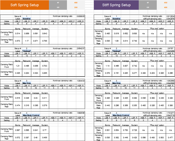
We then took this catalog to test at the Michelin Laurens Proving Ground, where we subjected our drivers to a blind sample of setups, recording their feedback and laptimes. Our fastest setup, "stiff+max grip(+2)", gained us almost a 5% lap time improvement when compared back to back with our original baseline!

A sample of driver feedback notes from the proving grounds test
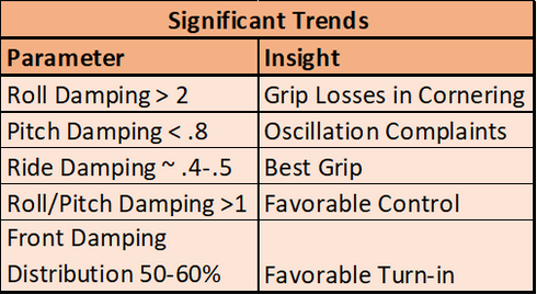
Looking through the time sheets and driver notes, we were able to extract some key trends across multiple setups:
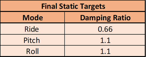
After a final discussion with the drivers, we settled on our final damping ratio targets:
Suspension Concept Selection
With stiffness and damping targets selected for all three suspension modes, the final step was to select the suspension configuration that would allow us to achieve as many of these targets as possible. Three main concepts were considered:
1) Corner-spring suspension with anti roll bar
2) Pitch-roll decoupled suspension
3) Third-spring suspension with anti roll bar
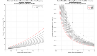
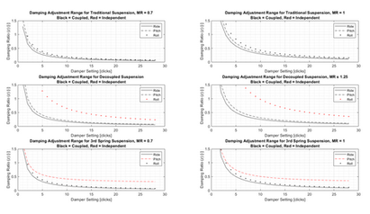
The available range of feasible geometries is limited by the range and resolution of our springs and dampers, and each configuration has its own trade-offs of both adjustment range and achievable resolution. Broadly speaking, there is a direct correlation between the ability to independently adjust all modes and the expense of cost, weight, and complexity. This can be shown in the following plots, which summarize a design exploration comparing motion ratio to resulting adjustment resolution using our existing hardware. For the traditional (corner-spring) suspension, each damper is responsible for all three modes, forcing a compromise.


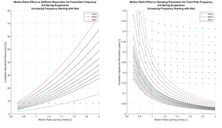
Since our Ohlins TTX25 dampers use shim stacks to adjust damping, the resulting adjustment curve is exponential, and the lower down on the curve we can be, the better resolution we can afford. This conflicts with the stiff spring/damper setting desired to improve spring resolution. These plots were therefore used to generate pairs of potential design solutions for each configuration - one with lower motion ratios to favor stiffness resolution and one with higher motion ratios to favor damping resolution.

A compilation of feasible design configurations
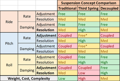
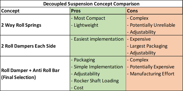
The table below summarizes the primary trade-offs between all three suspension configurations. The bolded parameters represent the characteristics that we prioritized the most.

Ultimately we made the decision to implement a pitch-roll decoupled suspension. While a third spring concept had the most overall freedom to make independent adjustments, the decoupled configuration was the best setup for making precise and independent roll adjustments. Since roll stiffness and damping are critical in determining both the transient and steady state balance of the vehicle, it was important for us to maximize our adjustment range and resolution for that mode more than heave or pitch. Ultimately, the decoupled suspension offered the best compromise between desired adjust-ability and complexity of implementation.
Typical decoupled suspensions employ a bi-directional spring and damper element, which can introduce cost and complexity to develop. Other teams have worked around this by implementing two roll units, one which actuates in either roll direction, but this is a heavier and larger solution. We decided to use an anti-roll bar (ARB) for the relative simplicity, packaging freedom, and cost to develop. As a bonus, shifting the ARB pickup points to the pitch rockers enabled us to minimize torsion loads across the actuation axes, minimizing weight and compliance.
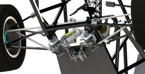
The actual design of the rocker geometry and mounting was carried out by other members of the team, so I will not discuss that work here. I will, however, include some pictures of the final assemblies for your viewing pleasure:
Future Development
Future development for this project is largely limited by the availability of information available about the operating window of the aerodynamics package. With that being said, I can still comment on which areas I would want to explore first:
1) Wheel rates and damping: Ride height control is a critical piece of the puzzle that is missing from this analysis, with limited CFD data to predict the effect on aero performance. With this information, there is an important trade-off to be made between ride height consistency and mechanical grip. This will open up the opportunity to move past stability and actually explore downforce optimization, which can bring significant gains in performance. Currently, this is analytically beyond our capability - we lack the CFD data, and our suspension ride models are still being fine tuned and correlated to the Ohlins shaker rig data. In the meantime, however, this is still something that can be explored with extensive on-track testing, which will generate useful data to compare to once our modeling infrastructure catches up.
2) More extensive aero-mapping: With more data on the aerodynamic sensitivity to pitch, roll, ride height, yaw, and velocity, we can construct a clearer picture of the ideal operating conditions to shoot for. This can lead to more informed decisions about target pitch and roll rates, as well as actually using rake and ride height as a setup tool.
3) Expanding exploration of stability and control: For Tiger22, my analysis of stability and control was limited to straight line trim and longitudinal acceleration scenarios. While still valid for making comparisons between configurations, this misses scenarios such as trail braking, maximum cornering trim, and change of directions, where stability is most critical. This will take some development in my numerical solvers, which was why it was not included for this design iteration. The current analysis had a very high insight:investment ratio, which was why I went down this path, but I look forward to continue to explore this.